PLEASE NOTE: NONE OF THESE POSTS ARE MENT TO BE USED AS A GUIDE OR AN INSTRUCTION TO PERFORM ANY WORK ON A BOAT. THE AUTHOR DO NOT GUARANTEE FOR ANY INFORMATION PROVIDED ON THIS ENTIRE BLOG!
Here you can find a lot of good information:
http://www.pbase.com/mainecruising/boat_projects
The project list I brought home from the week in July 2013:
- Repair or replace the rudder
- Install the maintenance kit for the dripless shaft seal
- Replace the battery charger
- Maintain or replace some of the thru-hulls
- Figure out the state of the batteries and the battery charging system
- Rebond the cables in the bilge to the keel bolts
- Replace the waste water hoses
- Buy and install a rail mounted barbecue
- Have the sails inspected and re-stitched where needed
- Polish and wax the hull
- Figure out a good solution for a dodger (we have a bimini-top only)
- Resolving the issue with the tank monitor
- Changing the filters, the motor- and the gearbox oil
- Replace some of the instruments
- Remove the TV-set and close the opening or insert a new TV
- Test and replace the bulbs on the engine control panel, replace the rubber booths
- Check and update the safety equipment
- Check the dinghy
- Replace pelican hooks at the lifelines
***************************************
Installing a dinghy davit system (March 2016)
To get rid of the dinghy on the foredeck, and allow an easier drop and lift of the dinghy, I decided to install a davit system. The positioning and installation wasn't that easy, since there is the radar dome in the way somewhat. I did just not want to relocate the dome. So I needed to find a suitable system, fitting in to the tight place, allowing me to rise the dinghy high enough, to have access to the water even when the dinghy is up, and which is strong enough, to support a solar panel, which should be one of our next projects.
I ordered the strongest version including a base extension of 12 inches. All arrived as promised. But when I tried to find the right position for the installation, it turned out, that I needed longer base extensions. After running to all possible stores and shops in the Stuart area, no-one could simply the 11/4" tubes with the 0.125" wall thickness. So I called Martek again. Kevin did a great job. He prepared the 23" extensions the other day and shipped them right to the boat yard.
It was the perfect length for our situation. the installation of the system was straight forward and with the help of Bob, the owner Windsong II, and a very skilled mechanic, the system including the struts and everything was installed by the end of the day. The next day, I only needed to drill holes in to the tubing and secure the fittings and tubes with stainless pop rivets. The system ist very sturdy and strong. So it was about time to detail out the installation of the solar system....


***************************************
Installing a solar system (March 2016)
Power consumption on a sailboat is an important subject. All the appliances and devices, which became "indispensable" these days, ask for a lot of electrical power. The fridge alone draws about 6.5 amp/h. We just got rid of the built in diesel generator. The unit was built in deep in to the aft bunk, where maintenance was merely impossible. This is probably the reason, why the unit stopped from generation power. I decided to not to replace the electrical part, which would have cost a couple thousand dollars. The unit was pulled in December 2015. I had t find a way, on how to keep up, with the power consumption, while being at anchor. I think, our daily consumption is around 100 amp/h. So we had the davit system in place and this offered a great platform to install a solar panel.
I did some research and ended up with a SolarWorld 285W panel and a Blue Sky 3000i MPPT controller including a remote display for the controller. E-Marine Systems in Ft. Lauderdale provided a great support in laying out the system and had all material on stock. So there we went and returned with another car load full of material, that had to be installed. The installation was straight forward and the way the davit system was set op, it provided a very easy way to place the panel on top. It took us one day to run all the cables, installing the controller, the remote, fuse etc. Already at the end of the day, the system started to charge the batteries.


On cloudy days, we still can run the Honda 2000i generator, to bring the batteries to a full load, or use the microwave, heat the water up, or even run the AC!
***************************************
Replacing the blocks at the mast base (November 2015)
The old blocks at the mast base were cracked and despredly needed a replacement.


I did some research and found several possible replacement parts. All of them were priced in the $80.- range per block. So I decided to see the local rigging company and ask for their recommendations. They recommended me to user the blocks from Garhauer. The blocks are stainless steel, have ball bearings and are very competitive priced. About $40.- per block were due at the end. The replacement was a snap. I did reuse the springs and the pins in the mast base. I'm very happy with the result!
***************************************
Replacing the divider wall between the freezer and the fridge (November 2015)
The dividerwall between the freezer and the fridge was originally made from wood. Obviously not a wise choice! The water from the freezer drains under the divider wall in to the fridge compartment. Thus, the wall is always somewhat in contact with water. After all, the lower portion of the wall has rotten and needed to be replaced.

The old divider wall


The compartment when the divider wall was removed
The shape of the wall promises a lot of fiddling, trial and error. First of all, I had to decide, what material should be used for the new wall, and how the wall should be designed. After considering several different material, I decided to build the wall as a sandwich construction, from Polyamyde sheets on the outside, mounted on a frame of Polyamide profiles. The cavity shall be filled with extruded Polystyrol.
I made a pattern of the existing wall by transporting the shape on to a large piece of paper. Than I fitted the first cover sheet. It was a difficult piece of work an took more than a day to complete. Then, the frame was constructed and the second cover plate was made. Once the wall did fit in, it was time to mount the plates for the pneumatic cylinders, the ventilator etc. Finally, it was time to fix the cavity with the insulation.

The cover plate with the frame partially in place

The insulated divider wall
By now, all is installed. I only need to finally seal the dividerwall against the box.
A picture of the end result will follow...
A picture of the end result will follow...
**************************************
Replacing the water heater (November 2015)
The onboard water heater did not look very clean anymore. After reading a frightening story from boiler of an other Hunter owner, I thought, it will be a good investment, to replace the water heater as a precautionary measure.

Well hidden under the settee...

The front does not look very promising!
I bought a new Seaward 6 gal. 110 VAC water heater with an integrated heatexchanger (at rear). Removing the old unit required to remove part of the settee. Hey, it's a boat! Working in inaccessible areas and needing to remove a bunch of parts, just to gain access ist part of the joy :-(
Once the old heater was out, the installation of the new unit was straight forward. Just until I wanted to replace the old fittings (plastic). I tired to buy replacements for the fitting. But then I've been told, that the manufacturers of the installed system went out of business some years ago. The systems were always leaking... Wow, I just learned, what potentially the next project might be. Luckily, my installation does not leak. So I bought some brass fittings and and some Shark couplings.


After about 5 hours, the new boiler was installed and connected.
**************************************
Waxing the hull (April 2015)
Some time ago, I considered, to polish and wax the boat myself. Due to the numbers projects, the long time, since the boat has ben polished and waxed and the little time we could spend on the water so far, I decided, to leave it for someone else.
In October 2014, I had the hull and deck compounded and waxed by a professional detailing company. In contradiction to my now wracked bank account, the boat really looked nice and all the dull surfaces became nice and shiny again.
Knowing, that the sun in Florida can do bad to the gelcoat pretty quick, I had to consider to wax the boat from now on from time to time. Already a while ago, I bought the starter kit from Shurhold Industries, including a dual action polisher, compound, polish and a couple of different pads to work with. I did not use this equipment so far. But now, I decided to give it a try and making sure, the investment in the gelcoat get not burned off by sun.
So I washed the hull thoroughly, let it dry, and startet to wax the hull from the rub rail to the waterline. I used the dual action polisher with the waxing pad and the polishing wax from Shurhold. I was skeptical whether the result would be as expected and advertised. I thought it would take me about two days to complete the job. But I made very good progress. Overall, it took me 30 minutes to wash the hull and another 3 hours to polish it.
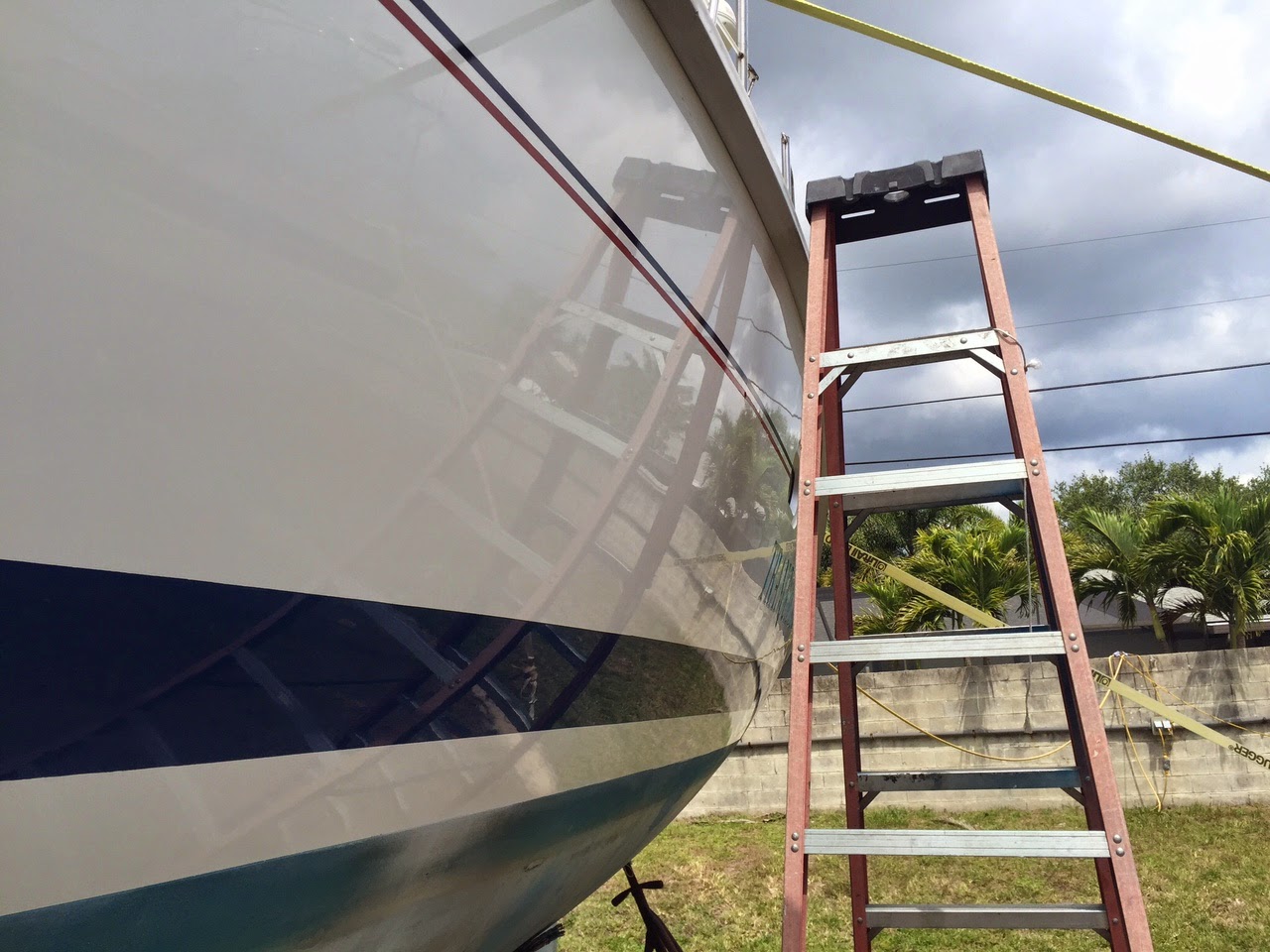
This is the outcome of 3 1/2 hours work. I'm very satisfied with the result. The equipment and the products proofed to work very well. So the deck and arch will be on the to-do list for the next visit.
Some time ago, I considered, to polish and wax the boat myself. Due to the numbers projects, the long time, since the boat has ben polished and waxed and the little time we could spend on the water so far, I decided, to leave it for someone else.
In October 2014, I had the hull and deck compounded and waxed by a professional detailing company. In contradiction to my now wracked bank account, the boat really looked nice and all the dull surfaces became nice and shiny again.
Knowing, that the sun in Florida can do bad to the gelcoat pretty quick, I had to consider to wax the boat from now on from time to time. Already a while ago, I bought the starter kit from Shurhold Industries, including a dual action polisher, compound, polish and a couple of different pads to work with. I did not use this equipment so far. But now, I decided to give it a try and making sure, the investment in the gelcoat get not burned off by sun.
So I washed the hull thoroughly, let it dry, and startet to wax the hull from the rub rail to the waterline. I used the dual action polisher with the waxing pad and the polishing wax from Shurhold. I was skeptical whether the result would be as expected and advertised. I thought it would take me about two days to complete the job. But I made very good progress. Overall, it took me 30 minutes to wash the hull and another 3 hours to polish it.
The ladder mirrors in the waxed hull
This is the outcome of 3 1/2 hours work. I'm very satisfied with the result. The equipment and the products proofed to work very well. So the deck and arch will be on the to-do list for the next visit.
***************************************
Replacing the electronics (December 2014)
Everyday, we take advantage from the fast improvements in electronics. The nowadays gadgets offer an almost endless variety of apps and tools, to make boating easier and safer. Unfortunately, the equipment on Tranquilizer dates from 1999 and is not capable, to interface with the new digital world. It is not even capable to connect with the internet. In addition, many displays got burned from the sun. New equipment could not been added to the existing installation without loosing some important or at least wanted functionality.
During a boat show in September 2014, I spent most of the time to evaluate the pro and con's from the different brands, and tried to find out, how easy it would be, to use the new electronics with some of the installed equipment, which I did not want to change, such as the autopilot's electric drive. Tranquilizer came with the following equipment:
Interfacing electronics, integrated in the SeaTalk Network:
- Autohelm autopilot course computer (under deck)
- Autohelm ST7000 autopilot control unit (at helm)
- Autohelm rudder position sensor (under the transom)
- Autohelm wind instrument (at helm)
- Wind transducer (mast top)
- Autohelm depth instrument (at helm)
- Depth transducer (through hull)
- Autohelm speed instrument (at helm)
- Speed transducer (through hull, retractable)
- Raymarine RC345 chart plotter (at helm)
- Autohelm multifunctional display (at nav station)
- Autohelm navdata display (at nav station)
- Standard Horizon DSC VHF (at helm)
Non interfacing:
- Rayethon SL70 radar (at helm)
- Radardome (on a post aft port)
After a period of research an evaluation, I decided to go with Raymarine. The reasons were:
- Good instrument selection for sailors
- The new autopilot course computer seems to be very good
- Compatibility with the the autopilot electric drive
- The possibility, to keep some of the instruments and transducers
II decided, which instruments I will replace and which I would keep and integrate. The next step was to draw the network layout. After all the conceptual work was done, I was ready to order and took advantage of the additional discount, offered during the St Petersburg boat show in December 2014.
The new set-up was designed like this:
Interfacing electronics, integrated in the SeaTalk NG Network:- Raymarine ACU 400 autopilot course computer (under deck)
- Raymarine P70 autopilot control unit (at helm)
- Raymarine rudder position sensor (under the transom)
- Raymarine i70 multifunctional instrument primary for wind (at helm)
- Wind transducer (mast top)
- Raymarine i70 multifunctional instrument primary for speed and depth (at helm)
- Depth transducer (through hull)
- Speed transducer (through hull, retractable)
- ITC5 convertor for the transducers
- Raymarine A127 multifunctional display as chart plotter and WiFi connector (at helm)
- Raymarine i70 multifunctional instrument (at nav station)
- Standard Horizon DSC VHF (at helm)
Non interfacing:
- Rayethon SL70 radar (at helm)
- Radardome (on a post aft port)
- Standard Horizon DSC VHF (at helm) to be replaced, as soon as there are more DSC/AIS
VHF radios on the market, interfacing directly with SeaTalk NG / NMEA 2000
During our holiday in December 2014, we started to pull the old instruments and installing the back bone network cables throughout the boat. While pulling the instruments, I tried to pull the old network cables as well. This allowed me additional room in the extreme narrow tubes, in which most of the cables run from and to the AC and DC distribution panel. I did not want to open the tube underneath the helm pedestal, where many of the cables for the electric drive of the autopilot etc. running through. The concept of the new SeaTalk NG network from Raymarine was very beneficial. We only had to install one relatively thin cable, to integrate all the components. The best thing was, that the power supply comes through the network. So only one connection to the DC power supply was required, to power-up all instruments, and another power supply was needed for the autopilot's course computer.
The cutouts for the new Raymarine instruments are larger than the existing one for the Autohelm instruments. We did not need to close any GRP surfaces. This was a big advantage! Initially, I wanted to save all transducers and integrate them in the new system. Unfortunately, it turned out that, the wind transducer was broken and did not provide a constant and accurate signal (as a result from the standing rigg replacement), the speed transducer was not operational (I already new this from the survey), and the cable from the depth transducer was tied behind the blinds of the bathroom with cable ties and could not be pulled.
We lost almost one day, to pull back all the cables, and ended up in not being capable to pull the most important one, the depth transducer cable. The depth transducer cable is the only cable which you cannot shorten, cut, extend, splice etc. It is part of the transducer and the unit is tuned together with the original cable. So we had to buy three new transducers. Lucky the boat was sitting in the dry.

Cutting out the new openings for the instruments

The old helm station

The new helm station

The new nav station
The installation of the instruments is very straight forward and the connection to the network as easy as 1,2,3! The installation took us 25 hours and the new Dremel (with accu) proofed to be a fantastic tool. I decided, to have the boat yard to install the through-hull transducers. They will be in place, when we will be there for the next time. The wind transducers was installed by the company, which replaced the standing rigg. All I could test, worked flawlessly and most important, the first time.
So we now only need to define the information, to be displayed on each and every instrument and to go through the installation and calibration process for the new autopilot. This will be on the list for our next visit. Overall, the project was on the expensive side. But I'm happy with the result. we now have the instruments we wanted and I hope, the new autopilot is keeping up with the high promises made through advertisements and reports from many owners! So far, I'm happy with the decision I made, to go with Raymarine.
***************************************
It was a bit of a challenge to find the right fittings to connect the different parts. But after stopping by at three marine suppliers and Home Depot, I finally found all what was required. The assembly is straight forward. Because I mounted everything on a acrylic mounting plate, the unit can be stored everywhere and I did not need to find a place to install it permanent.
Even with the copper lance, it is a bit tricky to reach all the way down to the bottom of the tank. I think I'll assemble a connector to use the tank's outlet for the generator and the engine as well, just to make sure, that I won't miss any water or dirt in the tank, when polishing the fuel for the next time, knowing, that bleeding the fuel lines then would be required.
But the result after a couple of hours fuel polishing was surprising. Zero water, zero dirt, algae etc. The bowl of the filter still looked was very clean. The filter element it selfs was still pretty clean too and I checked several times the flow of fuel. Probably it was not necessary to polish the fuel. But now I know, that the fuel in the tank is clean, giving me piece of mind.
***************************************


***************************************


***************************************


***************************************


The new pig tail hose and the new line connection to the valve
***************************************


***************************************


***************************************

***************************************

Polishing the fuel (December 2014)
After motoring a while on the St. Lucie River, I checked the inspection bowl of the Racor 500 fuel filter. I found a lot of water accumulating in the bowl (almost half full) and some black stain, possibly algae. The good new were, the filter is working fine and does separate water from diesel fuel. But what does de diesel in the tank looks alike?The previous owner has been up and down the ICW, sailed the Bahamas and Exumas etc. Did he always pumped clean fuel? Did he verify the quality of the fuel in the tank from time to time? Sure there was no answer to this. The access to the tank is difficult and you can't see whats really in there. So I assumed, the fuel has never been inspected for the past 15 years.
I decided to build a fuel polishing system and run through the whole amount of fuel, bunkered in the tank. And the research started again... I ended up buying the following components:
- Racor 500 fuel filter with a 10 micron filter insert
- Walbro FC 8 12 VDC fuel pump (approx. 28 GPH)
- 30 ft of fuel hose and fittings to connect the different sizes of the in- and outlets at the filter and the pump
- 6 ft of copper tube and fittings to build a lance
- Acrylic plate as a mounting plate
The idea was, to remove the hose and go through the nozzle of the tank inlet with a copper tube. This would allow me to reach all the way down to the bottom of the thank and pull the diesel, water and what so ever from there. The cleaned fuel would the be brought with the outlet hose back through the tank inlet nozzle. This would also result in a circulation of the fuel in the tank. The tank size is 51 gallons. So after 2 hours of polishing, theoretically, a full tank would be treated. The good thing on the set-up is, you don't need to bleed the fuel lines after polishing the fuel. There is always fuel in the tank and you don't disconnect the lines. So no air will find it's way in to the fuel line.
The pictures will follow
It was a bit of a challenge to find the right fittings to connect the different parts. But after stopping by at three marine suppliers and Home Depot, I finally found all what was required. The assembly is straight forward. Because I mounted everything on a acrylic mounting plate, the unit can be stored everywhere and I did not need to find a place to install it permanent.
Even with the copper lance, it is a bit tricky to reach all the way down to the bottom of the tank. I think I'll assemble a connector to use the tank's outlet for the generator and the engine as well, just to make sure, that I won't miss any water or dirt in the tank, when polishing the fuel for the next time, knowing, that bleeding the fuel lines then would be required.
But the result after a couple of hours fuel polishing was surprising. Zero water, zero dirt, algae etc. The bowl of the filter still looked was very clean. The filter element it selfs was still pretty clean too and I checked several times the flow of fuel. Probably it was not necessary to polish the fuel. But now I know, that the fuel in the tank is clean, giving me piece of mind.
***************************************
Why not to have a PVC Dinghy in the Tropics... (April 2014)
Ok, the 2005 West Marine Dingy came with the boat. It was a PCV boat. The previous owner did not use it for a while and stored it at his garage. So did I, because I did not want to have the Dinghy on the boat while she was stored on the dry for a couple of months.
In preparation to our planned sail trip in April 2014, I inflated the Dinghy for the first time, and I was amazed on how well it holds the air. Even after a week in my garage, the Dingy did not show any noticeable air loss. Fantastic - I thought!
So I deflated the Dinghy and took it to the marina to go for a test ride. I inflated it again, mounted the outboard on it and wanted to step in the boat. All of a sudden, my feet were in about 5 inches of water! The whole floor from the Dingy came apart!!!
What happened was, that the glued seam between the tubes and the slatted floor whent apart. The glue did not hold anymore.

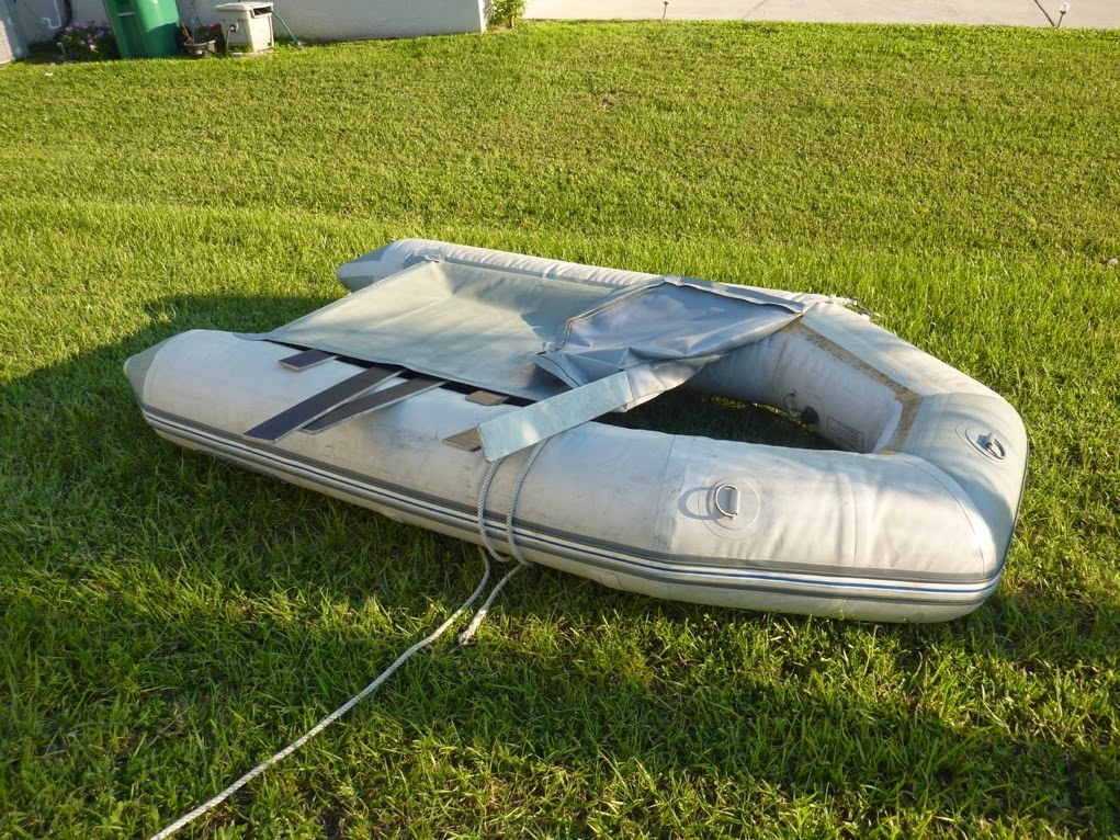
It does look good - doesn't it?
No, it does not look good at all!
I learned, that PVC inflatables are doing very good at holding air even after many years. But the glued seams are not doing well in warm temperatures. So if you tend to use the inflatable in the cooler areas or areas where it is warm during Summer only, then you'll be fine. If you tend to use the Dinghy in warmer regions such as South Florida or the tropics, the glue won't cope with it for long.
The inflatables made of Hypalon are doing much better in warmer areas. On the other side, they do not hold air as good as the PVC ones. I'll see, whether it is true or not.
So it was time to buy a new Dinghy. I did a lot of research and ended up with a 9.6' Hypalon inflatable, with wooden floor boards from Defender. I was in between the RIB's and the one with an inflatable keel. Because Tranquilizer is not equipped with davits, I decided that the Dinghy should have no larger rigid parts on it, to make it easier to stow it while under way. But I think the wooden floor boards over the inflatable keel will provide sufficient stability for the two of us.


***************************************
The all new Achilles 9' 6" Hypalon inflatable
The assembly is simple and quick. Event the hard wooden floor is easy to insert
I was a little bit concerned about the assembly of the dinghy. Will it be difficult and time consuming? Well, when assembling the boat for the first time, it my take a couple minutes more, because of the lack of experience. But already after setting up the boat for the second time, even the Admiral was pleased with the assembly process. We were able to inflate and assemble the boat, ready for departure within less than 15 minutes!
During the sea trial, we found out, that the new dinghy won't plane with the old two stroke 3HP Yamaha outboard engine. Maybe a good reason to look out for a new one...
Well, having said that, I decided to shop for a new outboard engine. In mid November 2014 I ended up with a Tohatsu four stroke 6hp from online outboards http://www.onlineoutboards.com. The support was just perfect! The only issue was the payment. Foreign credit cards are always a concern, when shopping in the US. Even a PayPal account, with a non US address, do very often not work. Finally, we found a way through and I could spend my money....
I ordered the engine together with the external tank. This aloe was a huge improvement over the old setup. No more mixing gasoline, no more gasoline spills when toping up the internal tank... And the engine was much cheaper than the lowest offers in any WM and other marine stores in the area.
Upon arrival in December, I had to find out, on how the new engine performs. So we went to well protected beach at the Indian River at the Hutchinson Island, geared up the boat made the motor ready to fire up for the first time. Immediately all the pictures from our last experiences with outboard engines came up... A whole new experience ! ... The engine startet with the second pull. After idling for more than 10 minutes, without a single stall, I decided to give it a try. I took the dinghy around, always near to the shore - just in case. Not a single problem. The motor's cover rattles a little bit, but not too bad. And then, I was allowed to increase the RPMs to 50%. The ride was pleasant and already fairly quick. The two of us were in the boat now. At 50% throttle, to boat did not plane. So after good while I dropped the Admiral and when out alone again. Now the ride was even faster and I felt like the boat is just about to plane. I tried to move the center of gravity forward and it caught up in speed. Then I steered some slight turns to the sides and here we go! The dinghy planed even at 50% throttle! Fantastic! Especially when considering the load of more than 300 lb (I'm 8'6" tall and everything but skinny).
So for all folks considering to buy a new dinghy, having restrictions to store a RIB inflatable on the sailboat and looking for an inflatable thats plane, here is the setup that works:
- Achilles 9.6, Hypalon, with wooden or aluminum floor, inflatable keel
- Tohatsu 6hp four stroke engine
-> Planes at least with 300 lb at 50% throttle!
To flush and store the engine at home, I considered to buy a dedicated stand at WM. Well the price tag keep me away from buying it. Instead I ended up at Home Depot and bought a bunch of wood and screws. All in all I spent $25 dollars and one hour of my well deserved holidays. And this is the outcome:
outboard engine stand
The only thing I need to add, is a higher bucket. Very simple and it works perfect. It is more than strong enough to store my two outboard engines on the stand at the same time.
Replacing the single lever throttle and shift controller (April 2014 - October 2014)
The original controller shifts very stiff. This makes the handling of the boat a bit tricky, especially when maneuvering at the dock.
The original MV2 single lever controller
I already tried to lube the control cables with little to none success. So after 15 years, I thought to replace the cables would be a good thing anyway. I ordered the Teleflex cables from Sailboatwoners. The shifter cable is the SBO part no.374022 and the throttle
cable is the SBO part no. 374023. These are both Teleflex CC3300 cables. One is 20ft (shifter) and
the other is 21 ft (throttle) long. I'll need to find out, which is the right length for the shifter and the
throttle.
While being on the boat in April 2014, I found out, that the cables themselves aren't that stiff. it has more to do with the shifter. So I decided to replace the single lever controller as well. SBO announced on heir website, that they have found a suitable replacement for the MV2 controller. The replacement part is manufactured by tele flex as well. According the drawings, it would not fit in to the cut-out. But it would require minor adjustments only. So I ordered the controller from SBO.
There is very little room for a different controller size. But I figured out, that the new controller will just fit in to the area. We will see in October, when I try to install the cables and the controller in one go. I'll update on this project later on.
Well, October came up and we had the chance to go to the boat again. The boat yard already noticed us, that the controller is that stiff, they were afraid to operate the boat! So it really was about time to change the thing.
I was suspicious about how difficult the replacing of the cables and the control unit itself would be. So the first day after arrival, we went immediately to the boat. I started to figure out on how the cables are running through the boat. The cables are running from the engine and gearbox in the center challis next to the exhaust hose to aft. The passage underneath the bulkhead is easy, since Hunter created a small tunnel underneath it. The difficult part is to run the cables from the aft compartment through the deck in the helm pod.
We marked the throttle and the shifting cable, and started to replace from the helm side one cable after another. I ordered the cables and the controller unit from SailBoatOwers. You can see the types on the picture below. The shifter cable is one foot shorter (20ft) than the throttle cable (21ft). The length do fit perfect, as long as you make sure, you are inserting the cables from the port side in the tunnel underneath the bulkhead.
The reason why the controller was so stiff, was found quickly...
The old throttle cable was corroded and bursted, just underneath the helm station
The new cables
I did replace the adapter for the morse cables at the gear box to make sure everything is new again.
The new controller after installation
The cut out was almost perfect for the new controller. A little trimming and the new unit fitted in place just fine. The next day I finished connecting the cables, installing the controller and adjusting the cable length as required. Of course we did seal the feed-through of the cables to make it water-tight.
All in all a very satisfying project with a very god result - the controller handles now like butter, both, for shifting and throttle! It took us about 8 hours to complete the project. Once you have installed the new cables, it is simple as 1-2-3!
***************************************
Replacing the Wema tank level indicator (April 2014 - October 2014)
Tranquilizer has two holding tanks (1x45 gal. underneath the bed in the aft cabin and 1x45 gal. underneath the bed in the fwd cabin.), three water tanks (1x51 gal. underneath the transom, 2x47 gal. underneath the settees in the saloon) and one diesel tank (50 gal.) underneath the transom. The original Wema tank indicator has several issues. First of all, the cover of the power switch is broken. When switching between the different tanks, the level is sometimes indicated, sometimes not. I think the problem is corrosion on the electrical contacts inside the Wema unit. So the readings do vary when wiggling on the selector switch. For some tanks, the reading is always the same, no matter what the level in tank really is.
The installed Wema unit
The size of the new Legacy Profile Series 8 unit should perfectly fit in place, without the need to drill new holes or to adjust the cutout in the wood.
So I decided to fix or replace the unit. I found no easy fix or replacement on Wema's website. But I found many positive entries in the forums, talking about the tank monitor from New Providence Marina Systems, distributed by Ferriello (you can follow this link www.ferriellosales.com). The good thing on this system appears to be the capability to use all existing working tank sensors, which are still operational in my boat. I expect the sensors in the holding tanks to be seized. Thus I've ordered the Profile Series 8 unit (6" size) and a set of foil sensors, to be mounted on the outside of the holding tank. In addition I need to buy the recommended wire, the connectors etc.. So all the parts are awaiting me in Florida, to be installed on my next visit. According to the installation manual and the reports from other owners, it should be straight forward installation.
Well, we all know, how this could end up with boats... I think I'll prepare my self for a lot of tiny little problems, sweating and some swearing. Just for the case that I'm wrong, I'll bring a couple beers with me, to celebrate the day!
I'll update on the progress and the installation experience when I'm back on the boat this fall.
The follow-up to this:
The installation of the Legacy tank Monitor went smoothly. The first step was to label all the wires and to find out, how the existing panel was hooked up. To mount the new system, I only had to trim the corners of the existing cut-out for the panel a little bit and the new panel fitted in just perfect.
Then it was about connecting the wires to the new system. All the existing sensors appeared to be a float type sensor. So I had to use the resistors, which came with the system. For the waste tanks, I had to install new foil sensors on the outside of the tank. This was a bit of a job. I had to run a cable from the panel to the tank in the front and the stern. Installing the new cables was the most difficult part in this project. Finally I found engulfed ways through the boat to run the cables. The installation of the foil sensors was easy and straight forward again.
After connecting all the sensor with the panel, it was time to power up the system and go through the very straight forward setup and calibration process. I had not the chance to finalize the calibration process because I did not empty the tanks to set the empty calibration point as well. But this can be accomplished when I'm able to use the boat for the next time. Still the new system is already fully operational.


After all a very satisfactory result. Get me the beers!
The follow-up to this:
The installation of the Legacy tank Monitor went smoothly. The first step was to label all the wires and to find out, how the existing panel was hooked up. To mount the new system, I only had to trim the corners of the existing cut-out for the panel a little bit and the new panel fitted in just perfect.
Then it was about connecting the wires to the new system. All the existing sensors appeared to be a float type sensor. So I had to use the resistors, which came with the system. For the waste tanks, I had to install new foil sensors on the outside of the tank. This was a bit of a job. I had to run a cable from the panel to the tank in the front and the stern. Installing the new cables was the most difficult part in this project. Finally I found engulfed ways through the boat to run the cables. The installation of the foil sensors was easy and straight forward again.
After connecting all the sensor with the panel, it was time to power up the system and go through the very straight forward setup and calibration process. I had not the chance to finalize the calibration process because I did not empty the tanks to set the empty calibration point as well. But this can be accomplished when I'm able to use the boat for the next time. Still the new system is already fully operational.
After all a very satisfactory result. Get me the beers!
Replacing the engine room insulation (April 2014)
The insulation on the engine room cover and the cover over the gear box in the aft cabin was worn out and came loose. To avoid that any part of the insulation would touch the engine, I decided to replace the insulation. So I removed the old insulation, sanded down the remainder from the old glue and cut the new 1" insulation in to shape. Then I repositioned the rubber seal on the engine room cover and pressed the new self adhesive insulation in place.


Now all looks nice and I don't need to fear that the insulation could touch the engine, a spinning wheel or a belt.
***************************************The insulation on the engine room cover and the cover over the gear box in the aft cabin was worn out and came loose. To avoid that any part of the insulation would touch the engine, I decided to replace the insulation. So I removed the old insulation, sanded down the remainder from the old glue and cut the new 1" insulation in to shape. Then I repositioned the rubber seal on the engine room cover and pressed the new self adhesive insulation in place.
The engine room cover
The gear box cover
Replacing the alternator (April 2014)
From the experience of a empty batter bank after 6 hours motoring, when I brought the boat from North Palm Beach to it's current location, I knew, there must be something wrong with the charging circuit from the alternator. So I ordered a new alternator from Spider Marine (Spidermarine.com). To buy the new 60Amp alternator for $119.99 was way cheaper than repairing the old alternator. So I tried to replace the original alternator during my short visit in January 2014.
The first thing when working on the alternator is to disconnect all the batteries (start- and house bank!). The positive wire will always deliver the full available power from the batteries, if you fail to do so.
The first thing I found out was, that the size of the bolts from the old alternator were M10 (yes, metric!). Although they promised a bolt on replacement, the new alternator is made to hold in place by M8 bolts. So I decided not to enlarge the drill holes, but to get smaller bolts. Can you imagine, how difficult it is, to find these very long M8 bolts in the US? I lost one day, running from one hardware-, auto parts-, mechanics- and other stores. Finally I found the matching bolts. But as they considered these bolts as a very unusual size, the sold them in bulk only. - So if anyone need very long M8 bolts, I do have plenty!!!
Back on the boat, I installed the alternator and tried to connect the electric wires. But again it was not bolt on. The studs were marked different. I decided to not risk a false connection and thus a burned up new alternator. I had to contact Spider Marine again, but it was Saturday and I had to catch the flight back home. So I installed again the old alternator, not to risk anything when the marina put the boat back in to the water just before we come back in April.
Back home in Europe, I got in contact with Spider Marine again. They claimed that they never heard of any issues with bolt sizes before. However, they gave me instruction on how to connect the alternator properly.
This is the backside of the old Hitachi alternator
This is how to connect the new alternator from Spider Marine
When I got back in April, the first thing was to re-install the new alternator again. Happy that all worked well, I fired up the engine - and still got no charging power from the alternator. Frustrated from the result, I removed the new alternator and had it bench tested. There was nothing wrong with the new alternator. I called the electrician from the boat yard to help me finding the problem. After measuring all possible circuits etc. we still had no clue what the problem might be. So he recommended me to disconnect all wires from the alternator to the batteries, cleaning up the connectors, studs etc. and reinstall everything again. All done, but still no charing power.
I knew that the battery charging check light bulb on the engine control panel was shot. AND I told them about it! I sat there without any further ideas on how I could resolve problem. We should be on our cruise - but instead we were still sitting at the dock, trying to resolve issues with the alternator. So I decided to post the problem on Cruisers Forum. After a couple minutes I already got the first suggestions, questions and comments. The next morning, a member told me that with this particular setup (Yanmar engine, Hitachi alternator), the check bulb from the engine control panel do belong to the alternator's exciter circuit.
The engine control panel, originally manufactured by Seaward
The spare bulbs I've ordered
My question to this was: - Do I really depend on a light bulb?! -
Immediately I when to the boat, had the bulb changed (luckily I ordered the bulb already some time ago from Seaward!) and fired up the engine again - what a success! The alternator threw out the required 14 and something Volts!
***************************************
Ground tackle (April 2014 - October 2014)
While I was thinking about the targeted ground tackle, I noticed, that Tranquilizer was equipped with a (too) small CQR anchor. There are only about 60 feet of chain and another 150 feet of rope. There are two other anchors, both with a couple of frets of chain and some more rope only.
The windlass is a Lewmar Sprint Atlantic, which was not operational. I could hear the relays switching when touching the up/down button, but the mechanism was seized. The windlass did not seem to be maintained recently. So I decided to remove all the moving parts, to have the windlass cleaned, greased and reassembled. The parts did not come apart easily and it took me several hors to take the few things apart. A lot of rust and dirt had to be removed. Then I applied a nice Teflon grease and made sure, all the moving parts came loose and lubed. After I had the windlass reassembled, I pushed the button again and the windlass worked again!
So I had to decide on what ground tackle I would install. I already ordered another anchor. A Mantus 65lb anchor, made from galvanized steel. The Mantus anchor received many good reviews and I found the Mantus' website very educating and helpful. Knowing that the discussion about ground tackle can become very quickly very religious, I'll not discuss it any further here. But I'll report on my findings, as soon as we could get some experiences with it. In the Mediterranean, I always had between 180 and 300 feet of chain aboard. The anchorages were mostly in 15 to 25 feet. Although we never had to ride out any substantial storms at anchor, I always felt comfortable with this setup. So I wanted to have much more chain on Tranquilizer than it has right now.
The first thing I needed to know, was what chain would fit with the installed windlass and the Gipsy. So I could not finish up this job and had to figure out the type of Gipsy, installed on my boat.
Side view of the existing Gipsy on the Lewmar windlass
Top view of the existing Gipsy
Once again, I got in contact with Lewmar's customer service. As with previous questions I had to Lewmar, they replied very quick and the information was exactly what I needed. For the (discontinued) Lewmar Sprint Atlantic windlass, Lewmar sold two different Gipsys, The RC162 and the RC172. It is very easy to determine which Gipsy is installed on this type of windlass. If it has 6 openings then it is the RC162, if it has 7 openings, Then it is the RC172. I could almost not believe that some things on boats could be that simple....
I have the RC172. The best thing is, that the RC172 can work with many different types of chains. I figured out, that I'll go with a 5/16 HT (G4) galvanized chain. It has a work load of 3900 lb, which is not a bad value for the size of my boat. I have not decided yet, on how much chain I'll buy. But I think it will be 150 feet and additional rope, or 275 feet of cain. It depends on what the chain locker will be capable to carry. The additional weight on the bow is another thing I need to count in to my considerations.
October 2014
Well, i decided to order a half drum of 5/16" G4 grade chain from 1st Chai Supply. Taking the freight cost in to consideration, it was somehow the best offer I could find. After 5 working days, the chain arrived at the boat yard.
I placed the boat with the bow pointing to the dock, so I was able to access the anchor and the pulpit with ease. I removed the old chain and rope from the anchor and replaced it with the new chain. By that time, I also hat the chance to straighten out the stainless steel pulpit, which was bent from a obviously failed maneuver from the previous owner. In addition, I did replace the anchor roller on the pulpit and treated the bolt including the internal bushing in the roller with an anti-seize grease, to ensure a smooth operation for a long time.
The 275 feet of chain do fit easily in to the chain locker.

Now I will anchor with much more peace of mind. The only thing I will need to do, is to to attach a short length of rope at the end of the chain and attach it securely to the eye in the anchor locker. Compared to the HT chain, the rope will be easy to cut through, if I would be in an emergency situation and must get rid off the ground tackle immediately.
October 2014
Well, i decided to order a half drum of 5/16" G4 grade chain from 1st Chai Supply. Taking the freight cost in to consideration, it was somehow the best offer I could find. After 5 working days, the chain arrived at the boat yard.
I placed the boat with the bow pointing to the dock, so I was able to access the anchor and the pulpit with ease. I removed the old chain and rope from the anchor and replaced it with the new chain. By that time, I also hat the chance to straighten out the stainless steel pulpit, which was bent from a obviously failed maneuver from the previous owner. In addition, I did replace the anchor roller on the pulpit and treated the bolt including the internal bushing in the roller with an anti-seize grease, to ensure a smooth operation for a long time.
The 275 feet of chain do fit easily in to the chain locker.
The chain locker with the 275 feet of chain stored
Now I will anchor with much more peace of mind. The only thing I will need to do, is to to attach a short length of rope at the end of the chain and attach it securely to the eye in the anchor locker. Compared to the HT chain, the rope will be easy to cut through, if I would be in an emergency situation and must get rid off the ground tackle immediately.
***************************************
When searching for a replacement of the steaming light... (January / March 2014)
I knew I had to replace the steaming light on the mast. Trying to avoid to go aloft just to identify the exact type of light I would need to buy, I took a high resolving picture from the particular area on the mast. While looking at the picture, it was almost impossible to determine the proper part. But I found that the starboard spreader was not properly positioned.
Broken starboard spreader base
I was on a business trip in January 2014, when I called Mack Sails, to perform a rigg inspection (which I should have done before buying!!!). The briefing after the inspection was very quick - the spreader base is broken, the standing rig shows signs of beginning corrosion and the plastic inserts over the for stay on top of the furling unit needs to be replaced :-( That's BAD news!
The only good thing about it was, that I did not need to worry about the steaming light anymore. I had Mack Sails to weld the spreader, check all the other spreaders, replace the parts on the furling unit, replace the standing rigging and the steaming light (an LED type now).
Since we will be sailing a bit short handed, I decided to have Mack Pack installed on the very long boom. The Mack Pack is a Lazy Jack system including a sail cover with a zipper that can be operated from any position on the boom. You don't need to go to the mast or follow the zipper all the way. Very convenient and makes the covering of the sail a quick and easy task. Here is the link to their website: http://macksails.com/mackpack.htm
I'll post a picture from the Mack Pack installed on Tranquilizer later on.
By the end of the line, I was lucky that I detected the broken spreader. If we were gone sailing with a broken spreader, we might could have lost the boat or even our lives!
***************************************
Shower drain sump (April 2014)
The installed shower drain sump pumps were still the original ones. And yes, the compartment and the hoses deserved a thorough cleaning!
The old fwd Attwood shower sump pump unit
There are two sump pumps installed on the boat. The pump for the fwd shower worked, but no water was pumped overboard. The pump for the midship shower did not work anymore. So I decided to replace both units with new Rule 800Gph units.
The new aft Rule shower sump pump unit
The units do work well. But I had to figure out the reason why no water has been pumped out from the fwd unit. Even the new unit did not resolve the issue. The further investigations turned out that the hose from the pump to the through-hull above the waterline was clogged. So an easy fix. A thin steal rod helped to remove the dirt piece by piece while making sure, the line is not cut.
***************************************
Replacing the LPG hose and fittings (April 2014)
The installed LPG hoses became stiff and the way the hose was bent underneath the shut-off valve scared me!
The old pig tail hose
The old hose connection with a 90° fitting
The installation really needed an update. So I bought a new piggy-tail and a new connecting hose (20ft) for the oven. I also replaced the 90° fitting underneath the shut-off valve with a straight fitting.
The new pig tail hose and the new line connection to the valve
Now I only need to secure the electric wires and clean the compartment and another project is accomplished
One could think that LPG installation material is standardized and available everywhere. You will find out that they are built to a standard, but there are many different standards in the market. So make sure, the flared connectors are the correct ones, the connector for the LPG tank is of the matching type with your tank etc.
After all, I can use the LPG installation with confidence again, without worrying that propane leaking in to the boat. I might consider to install a gas alarm as well. Just in case...
***************************************
Removing the antique TV-set (November 2013)
The TV set which was on the boat, appear to be from the days, when we all admired Flash
Gordon's adventures!
The old TV set in place
We did not decide yet, whether we will have a TV on board. So for now, the opening needed to be closed.
The new cover with the TV set removed
The outcome is not to bad. I only need to replace the chromed screws by black coated ones.
***************************************
Replace pelican hooks at the lifelines (November 2013)
The pelican hooks are fantastic to quickly open or close the lifelines at the gates. The inner spring and the spike from two hooks were lost.

The shackles are made of stainless steel. There are many different types with different treads on the market. WM could not help in this case. So I found Bosun Supplies providing a very nice product range on stainless steel products. This link will lead you direct to the product on their website bosunsupplies.com 5/16 UNF tread pelican hook. The shape of the eye is slightly different from the original one, but they fit perfect.
Leaky exhaust muffler (November 2013)
The pelican hooks are fantastic to quickly open or close the lifelines at the gates. The inner spring and the spike from two hooks were lost.

The old pelican hook
The shackles are made of stainless steel. There are many different types with different treads on the market. WM could not help in this case. So I found Bosun Supplies providing a very nice product range on stainless steel products. This link will lead you direct to the product on their website bosunsupplies.com 5/16 UNF tread pelican hook. The shape of the eye is slightly different from the original one, but they fit perfect.
***************************************
Leaky exhaust muffler (November 2013)
Once the shaft seal was rebuilt, I wondered from where the clear water in the bilge is coming from - The boat sat on the dry! After investigating a while and chasing the water trail, I concluded that the only water source in that area could be the exhaust muffler. The cooling water from the engine runs through the micing ellbow in to the muffler. First I thought it could be the drainplug in the muffler. But the srew proved to be dry. I had no other choice than to remove the entire muffler. Th real issue was to loosen the 3", stark and stiff exhaust hose from the muffler. Below you can see the removed muffler, brought on deck.

The uninstalled muffler (bottom side) with clear signs of chafing
After sanding off the paint, the leak became visible. The muffler chafed on the hull and grinded down the fiberglass, binding the front plate of the muffler to the oval body.

The chafed area with the crack
I sanded off the paint on a larger area, inserted the screw to protect the tread in the muffler's body. After drying out the remaining humidity with alcohol and heat gun, I filled the gap with fiberglass and epoxy.

The glassed area
Finaly I covered the area with a larger patch in multipole layers to re-enforce the area. To prevent the muffler from chafing on the hull again, I attached a larger patch of felt on the muffler. Finaly I reinstalled the muffler and fixed it in place with expanding foam. I felt very lucky that I found the leak. The muffler is right beside the bed in the aft cabin and could have caused exhaust gases to enter the cabin!
Rebond the cables in the bilge to the keel bolts (November 2013)
I found some cables in the bilge which were not attached and the loose ends showed that they corroded off somewhere. Further investigations turned out, that these cables are part of the grounding system of the vessel. They bond the mast and other exterior parts to the keel.

Life could be so easy - if I only had a little more space to work with the huge crimping tool on the 2 AWG cables... After a long and sweatty while, I manged to crimp on the eye terminals. But it was far from fun nor was the result entirely satisfactory. It was very difficult to crimp on the terminal at all. It was not possible to make sure the terminal is watertight. So I think I have to add a good shrink tubing.
Maintain or replace some of the thru-hulls (November 2013)
As one result of the survey, some of the thru-hulls were in questionable condition. So I was prepared to replace some and maintain the remainder of the thru-hulls and the sea cocks. When I took a closer look at these safety relevant parts, I could see that some of the backing plates were rotten. Most of the sea cocks showed a developed verdigris.

After talking with the mechanics from the boat yard and deliberating the options, I decided to replace all throu-hulls and sea cocks below the water line. The old backing plates were replaced by new plates of G10 material. I decided to install thru-hulls with triangle flanges and a treadded adaptor to screw on the separate sea cocks.


This installation allows to change the sea cock, without needing to pull the thru-hull. You can see the concept when clicking the following link: http://www.groco.net/seacocks.htm
Changing all the thru-hulls and sea cocks was a high amount of money out of the pocket, but I hope I'm done with these things for a long time!
***************************************
Changing all the thru-hulls and sea cocks was a high amount of money out of the pocket, but I hope I'm done with these things for a long time!
Replacing the battery charger (November 2013)
The battery charger was still the original Guest 30A charger, allowing to charge two different batteries. Through measuring the output from the charger, we found out that there might be something wrong. No matter what charging state of the battery, the output remained always at about 6 amps. So I decided to change the charger. I was searching for a charger which allows to charge two banks (starter and house bank) independently and to have a remote charger monitor. The monitor allows to see from the nav station, what the charger is doing and allows to set the charging mode when necessary without accessing the charger compartment underneath the settee. The picture below shows the original charger.

After comparing many different products, I found that Sterling Power (website Sterling Power) offers a very good product for a reasonable price. The charger has all the features I was looking for and the remote unit is, compared to other products, sold at a reasonable price. The only concer was, that Sterling recomends to install the charger in a vertical position. Allowing suffient space for the cables and a good access to the charger, the height of the unit did not fit under the settee. So I talked to Sterling and they told me that a hirizontal installation is fine, as long as there is no chance for water entering the compartment (we all can imagine a situation, when water will enter any compartment..) and the air flow for ventilation is unimpeded.

The installation is easy and straight forward. The manual provide a step by step installation guide. I had to size up the cables, running from the charger to the battery switch. The charger is rated at 60Amp output. So I had to replace the cables with 4 AWG and a new upgraded fuse. The monitor was mounted at the nav station.
Installing the maintenance kit for the PSS dripless shaft seal (November 2013)The battery charger was still the original Guest 30A charger, allowing to charge two different batteries. Through measuring the output from the charger, we found out that there might be something wrong. No matter what charging state of the battery, the output remained always at about 6 amps. So I decided to change the charger. I was searching for a charger which allows to charge two banks (starter and house bank) independently and to have a remote charger monitor. The monitor allows to see from the nav station, what the charger is doing and allows to set the charging mode when necessary without accessing the charger compartment underneath the settee. The picture below shows the original charger.

After comparing many different products, I found that Sterling Power (website Sterling Power) offers a very good product for a reasonable price. The charger has all the features I was looking for and the remote unit is, compared to other products, sold at a reasonable price. The only concer was, that Sterling recomends to install the charger in a vertical position. Allowing suffient space for the cables and a good access to the charger, the height of the unit did not fit under the settee. So I talked to Sterling and they told me that a hirizontal installation is fine, as long as there is no chance for water entering the compartment (we all can imagine a situation, when water will enter any compartment..) and the air flow for ventilation is unimpeded.

The installation is easy and straight forward. The manual provide a step by step installation guide. I had to size up the cables, running from the charger to the battery switch. The charger is rated at 60Amp output. So I had to replace the cables with 4 AWG and a new upgraded fuse. The monitor was mounted at the nav station.
***************************************
PSS (PSS / PYI Dripless Shaft Seal), the OEM for the installed dripless shaft seal recommend to replace the bellow every 6 years. If the battery is close to the shaft seal, the advice to check the bellow even more frequently than you probably do anyway. The gas from the battery can cause damage to the rubber of the bellow. The bellow on Tranquilizer appeared to be in good condition. Just the tension has never been adjusted, causing the shaft seal "leaking" and sprayed a considerable amount of salt water in to the bilge. I ordered the maintenance kit from PYI (which belongs to PSS). You need to know the shaft size and the size of the shaft bearing (hull). In my case I ordered the part number 07-114-214R, which fitted perfect.

Before I could install the maintenance kit, I had to remove the rotor from the shaft to get access to the two o-ring seals. To remove the rotor you need to remove the coupling flange. This is the point where the problems started again… It was very difficult to separate the coupling flange on the shaft from the flange on the gearbox. Only by inserting bolts and pressing the flanges apart from each other by using counter nuts we could slowly press the flanges apart. At the same time you will need to push back the shaft to get enough space to remove the flange from the shaft. And again it was very difficult to get the flange off the shaft. It is unclear whether the flange was press-fitted on the shaft or the shaft was not machined to the proper size. Heat and gentle hammer strokes did help to get the job done. I bought a new flange for the shaft coupling and had the shaft machined to the proper size at a local shaft and propeller shop.

When we pulled the shaft, we noticed, that the cutlass bearing would need to be changed soon. So we also changed the cutlass bearing. And- NO, YOU CAN'T PULL THE SHAFT WHILE THE RUDDER IS IN PLACE...! So you I was lucky in a way that the rudder was removed already. Since the shaft was already out of the way, we did not need to use the special toll for pulling the cutlass bearing. But it's still a good idea to get informed first, how to exactly perform this job. I bought in some knowledge from the boat yard where the Tranquilizer is stored.
Overall I'm very happy that I have changed the shaft seal and the cutlass bearing. Beside of checking the bellow I should be fine with these important parts for a while. If the bellow would leak, you will be very likely facing a huge amount of water entering your to your boat.
***************************************
Replacing the rudder (November 2013)
As a result from the survey, I knew I had to resolve the issues with the ripped bottom of the rudder.


Like other owners who had to change the rudder, the releasing of the screws and the centre bolt caused a lot of problems. Stainless steel screws and bolts in aluminum threads are and never have been a nice combination - add salt water and you have the evil combination… I tried to work on the crews and the bolt with an impact driver, lots of various sprays and a shy amount of heat. It is difficult to work with a torch without risking to burn the gelcoat around the quadrant. Finally I found that I could lift the rudder by 4 millimeters, just enough to work on the old rudder post with a recipro saw. You can see the old rudder post underneath the cut away quadrant.

Now we could lift the boat with the travel lift to allow enough room under the rudder to pull it. Inserting the new lower bearing and installing the new rudder was easy. Just make sure, the lower bearing is glued in which the rudder in place to ensure proper alignment.
Here you can see the cleaned quadrant on the new rudder post.

No comments:
Post a Comment